Thông tin sản phẩm
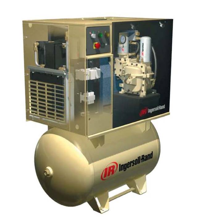
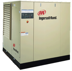
Tên sản phẩm: SSR 90-160KW DETAIL SPECIFICATION INGERSOLL RAND
Model: SSR 90-160KW DETAIL SPECIFICATION INGERSOLL RAND
Model: SSR 90-160KW DETAIL SPECIFICATION INGERSOLL RAND
SSR 90-160KW DETAIL SPECIFICATION INGERSOLL RAND
Đánh giá: 0/5 sao (trong tổng số 4 bình chọn)
Bình chọn của bạn:
Bình chọn của bạn:
SSR 90-160kW
Detail Specification
INLET AIR FILTER:
Inlet air filtration for the SSR is accomplished by a large 99.9% efficient at 3 micron and above,
dry type air cleaner. This is more than suitable for the vast majority of applications; however,
where high dust and dirt contamination is present, optional filtration systems are available.
COMPRESSION MODULE:
Since the airend is the fundamental component in any rotary screw compressor package,
reliability, performance and efficiency are determined, for the most part, by the design,
manufacturing tolerances and assembly of the airend itself. All other elements in the
compressor system are essentially support and monitoring devices, included to insure
dependable service and performance.
The rotors are manufactured from AISI-C-1141 forged steel. In larger size airends the
asymmetrical pro-file is developed through a unique two-step machining process. The first
step in the machining process develops the basic wrap angle pro-file and is a rough cut. The
second and final step is a finish grinding process, which insures a hard true rotor surface.
Rotor shafts are precision ground to tolerances within 0.0005 of an inch. It is during the second
step, that the sealing strips are ground into the female rotor. The function of sealing strips as
indicated by the name, is to seal the compression chamber to minimize leakage and blow-by.
Sealing strips are of-ten likened to piston rings on a reciprocating compressor. After the
machining process has been completed, each rotor is inspected on three axis for dimensional
integrity. The rotors are match-marked set prior to assembly in the rotor housing. The rotor
housings are made of close grain high quality cast iron. After machining, each housing is
dimensionally checked to insure accuracy.
Duplex Taper Roller Bearing Schematic
The bearing configuration used on all SSR models is the tapered roller bearing. The tapered
roller bearing essentially consists of constructing the roller elements, as well as the raceways,
so that lines drawn coincident with the working surfaces of the rollers and races will all meet at
a common point on the axis of the bearing. This allows the bearing to handle all loads, radial,
thrust or both. With this bearing configuration, the discharge end of the male and female rotors
are each equipped with a pair of tapered roller bearings offset at opposing axis for maximum
absorption of thrust and radial loads.
High quality cylindrical roller bearings are used to carry the radial loads on the inlet end of the
rotors. All bearings, whether thrust or radial, use premium cost vacuum degassed bearings,
which provide truer, harder running surfaces for both inner and outer bearing races.
Coolant dams are machined at the duplex taper roller bearing locations. The coolant dam
provides an area for coolant to collect or pond when the compressor is shut off. Upon startup
the taper roller bearing that is resting in coolant ponded by the coolant dam begins to rotate
and is immediately lubricated. Airends without coolant dams have bearing systems that
operate dry for approximately six seconds on start up.
MAIN DRIVE MOTOR-GENERAL
The main drive motor is exactly matched to the requirements of the SSR. Torque and load
requirements of the compressor were matched to specific design criteria that enabled the SSR
motor to develop peak efficiency and power factor at full load. This stated efficiency advantage
is illustrated if one were to compare SSR motor efficiencies with typical NEMA T frame motor
efficiencies; generally this advantage is 5%.
A. FRAME:
Motor frame and end brackets are of cast iron with integrally cast feet. This provides maximum
strength and rigidity for bearing support, uniform stator/rotor gap and flanged permanent
alignment of all mating parts.
B ELECTRICAL DESIGN:
Speed, torque and operating characteristics have been designed to match the load of the
compressor. Motor efficiency and power factor have been optimized to cover the entire
capacity range of the SSR.
C. BEARINGS:
Vacuum degassed ball bearings for the drive end and roller bearings for the discharge end
provide depend-able and reliable service. These oversized bearings have an average applied
life of 135,000 hours, which is approximately eight times greater than NEMA standards. Both
bearings are grease lubricated with bearing housings having inlet and relief fittings to simplify
the lubrication procedures.
D. INSULATION:
The SSR high efficiency motor has class F insulation as standard. That means it is rated at
continuous duty for up to a 115°C temperature rise. However, no SSR motor is ever applied for
a temperature rise over 90°C, a difference of 20°C. Ordinary competitive motors, on the other
hand, use the lesser class B insulation, rated for a maximum of 90°C rise. Further, they are
routinely operated with a temperature rise of 82°C or more, a difference of only °C. That’s
really significant, since the motor life expectancy is doubled with every 10°C reduction in
temperature rise. The extra conservatism built into every SSR motor means more reliability,
increased life, and a much more for-giving motor under adverse conditions. And even with all
these unique features, the SSR motor still utilizes NEMA* and IEC** design standards.
E. WIRING:
All windings and leads are copper with triple coats of insulating varnish to add extra margins of
protection to the driver.
F. TESTING:
During manufacture and assembly, 40 different tests and quality control checks are made to
insure SSR motors meets Ingersoll-Rand requirements.
INTEGRAL DRIVE ASSEMBLY:
In order to utilize the inherent efficiency advantage of the SSR motor and airend, it was
necessary to develop a means of efficiently transmitting power from the driver to the
compressor. The integral gear drive system was chosen because it is an efficient, reliable and
rugged design. Conservatively chosen speed optimizing gears are mounted on extended
shafts from the airend and motor. The flanged motor is doweled for permanent alignment to
the airend. The use of AGMA Class 11 gears allow the SSR airends to rotate at a specific
speed, which allows maximum airend efficiency. The gear housing is completely sealed
against atmospheric contaminants to insure life-time trouble-free power transmission. A
self-centering teflon impregnated motor shaft seal provides a positive system against leakage
to the motor winding. The entire assemblyis vibration isolated from the package.
LUBRICATION SYSTEM
A. COOLANT FILTRATION:
The full capacity coolant filter is a 10 micron spin-on replaceable element with pressure
bypass.
B. COOLANT/LUBRICANT HEAT EXHANGERS:
Integrally mounted aircooled heat exchangers are designed for ambient temperatures to
46°C/115°F. The core, fan and fan motor are all mounted and prewired on the end of the
compressor package. Watercooled coolers are shell and tube type designed to use fresh
cooling water at inlet temperature up to 32°C/90°F.
C. COOLANT/LUBRICANT TEM-PERATURE CONTROL (AIR-COOLED AND
WATERCOOLED UNITS):
The thermostatic control valve with three ports, (1) for the coolant from the cooler, (2) for the
coolant from the pressurized receiver/separator, and (3) for the coolant to the coolant injection
orifices, is mounted in the piping system. The temperature sensitive element controls the
quantity of coolant from each source, cooled and uncooled, necessary to provide the proper
injection temperature and assure fast warm-up
D. COOLANT INJECTION:
On rotors, the coolant is injected through multiple ports on the female rotor inlet side and
directed back toward the inlet cover. This insures the best possible presealing of the rotor, plus
an optimum mix of coolant with inlet air. Coolant is sprayed into the middle stages of the
compression cycle. To seal the inlet, there is limited injection at the female rotor. Full size
multiple ports give best flow cooling and sealing under a wide variety of operating conditions.
E. COOLANT/AIR SEPARATION:
After compression and discharge from the airend, the air heavily laden with coolant travels to
the receiver/separator. Entering through a tangential inlet, the air coolant mixture is directed in
a circular motion around the inside of the tank. The vortex or circular motion separates a major
portion of the coolant from the air through centrifugal force. The air is then directed through
baffles, which further reduces the coolant content. The vortex action and baffling results in a
pre-cleaning of the compressed air, prior to entering the separator element.
Separator element is a molded fiberglass two-stage reinforced separator. On all size SSR
compressors, the carry-over, after the separator element is 3-5 ppm. Compressed air then
enters the optional aircooled or watercooled aftercooler, where the carryover of 3-5 ppm will be
further reduced by the aftercooler and condensate separator to a final carryover figure of 2
ppm.
Hence, when calculating coolant makeup for SSR compressors, always use 3-5 ppm by
weight. Due to the conservative sizing of the separator element, there is a minimal 2 lb.
pressure drop. This reduces the required HP to move the air through the compressor system.
CONTROL MODULE-GENERAL:
The SSR compressor includes a microprocessor based control module which provides for
starting, capacity control, operating control, and safety control of the unit. checks are made to
insure the SSR motors meet Ingersoll-Rand requirements.
A. COMPRESSOR/CAPACITY CONTROLS:
As standard the SSR is provided with Intellisys Control on-line/off-line with upper range
modulation control. On-line/off-line allows the compressor to operate at 2 points on the
capacity curve. The first is 100% full-flow and the second is 0 flow. The on-line/off-line control
is a power savings mode of operation. The unloaded operation pro-vides for immediate
compressor system blowdown to minimize power requirements. The compressor will
automatically reload to 100% capacity when the sys-tem falls to a predetermined pressure.
Upper range modulation combines the benefits of conventional modulation control with the
power savings advantages of on-line/off-line control. This mode of control is automatically
used when the demand for air is expected to be relatively high as compared to the compressor
capacity. As set at the factory, each SSR will modulate from 100% capacity to 60% capacity.
When the system calls for less than 60% of capacity from the compressor, the unit will
automatically unload and blow down to atmospheric pressure, again reloading if the system
pressure decays to a pre-determined setting.
INTELLISYS READOUTS
Display Standards
•Package discharge pressure
•Package discharge temperature
•Total hours/loaded hours
•Airend discharge temperature
•Injection coolant temperature
•Sump pressure
•Inlet filter condition
•Inlet vacuum
•Coolant filter condition
•Separator element pressure drop
•Modulation % load
Adjustable Operating Parameters
•Off-line pressure
•On-line pressure
•Star Delta transition time
•Stop delay time
•Auto start and stop shutdown time
•Auto start and stop on/off
•Sequencer control on/off
•Remote start and stop on/off
Fault Warnings
•Change inlet filter
•Change coolant filter
•Change separator element
•High airend discharge tempera-ture
•High airend discharge pressure
•Sensor Failure 4ATT
Fault Shutdowns
•High airend discharge tempera-ture
•Low unloaded sump pressure
•Low loaded sump pressure
•Remote start failure
•Remote stop failure
•Starter failure
•Main motor overload
•Fan motor overload
•Reverse rotation
•Inlet control
•Sensor failure
•Microprocessor failure memory fault
•Control power loss
Sản phẩm cùng loại
Model: MÁY NÉN KHÍ TRỤC VÍT INGERSOLL RAND M45-75KW COUGAR
Model: MÁY NÉN KHÍ TRỤC VÍT INGERSOLL RAND TWO STAGE R90-160 KW XE
Model: MÁY NÉN KHÍ TRỤC VÍT INGERSOLL RAND TWO STAGE R90-132KW
Model: MÁY NÉN KHÍ TRỤC VÍT INGERSOLL RAND R90-160KW BIẾN TẦN
Model: MÁY NÉN KHÍ TRỤC VÍT INGERSOLL RAND RS30 -37 I ( CHINA)
Model: MÁY NÉN KHÍ TRỤC VÍT INGERSOLL RAND SMALL UP (4-11KW)
Model: MÁY NÉN KHÍ TRỤC VÍT INGERSOLL RAND R30N-37N (NEW 2015)
Model: SSR 45-75 kW Detail Specifications Ingersoll Rand
Model: MÁY NÉN KHÍ TRỤC VÍT INGERSOLL RAND R90-160 KW XE
Model: MÁY NÉN KHÍ TRỤC VÍT INGERSOLL RAND M90-160KW SG COBRA



 Công Ty TNHH Thuơng Mại Dịch Vụ Xây Dựng Cơ Điện HOÀNG NGUYÊN